A simple open source air quality sensor : Round One - Fight !
15 Jun 2022ElectronicsCADFusion360StemmaQTI2C3D Printing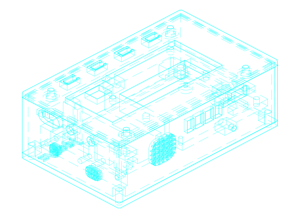
Motivation #
A few years ago, I came across this video on the effects of carbon dioxide on concentration :
This was eye opening : I had noticed my concentration level decreasing in closed classrooms, but this was much more alarming than I thought.
My first reaction was obviously to open my window and let some fresh air in, but I was also curious : how long does it take in my apartment or in my room for levels of CO2 to reach 1000ppm ?
So I needed data, which means I needed a measurement device. I looked online for CO2 measurement units but I could not find one that would suit my very special requirements.
I wanted :
- a small device with an e-ink display that I could set and forget in my appartment
- that would display true CO2 levels (more on that later) and levels for a few more gases and particles
I also wanted to be able to use the device to measure and log concentrations while on a city trip for example.
But my biggest constraint was that I did not want to buy yet another electronic gadget that would stop working after a few months and that would require a lot of work to repair.
So ... I decided to build one.
Sourcing components #
Still, I did not want to buy components that would also be difficult to use or maintain, and that would quickly become e-waste. Fortunately, there was a new line of products that was perfectly aligned with the idea of quick projects with components that can be repurposed later : Adafruit's StemmaQT/Sparkfun Qwiic ecosystem
This ecosystem of products uses a single Molex connector to transmit power (3V) and data across components. It relies on the I2C protocol, and makes it extremely easy to assemble a project/prototype. Furthermore, with CircuitPython/MicroPython (a version of Python for microcontrollers) now fairly popular, there are Python libraries for most I2C sensors and actuators on the market today.
I was thus certain that I could reuse most of the StemmaQT/Qwiic components in later projects, should I decide to diassemble my future air quality measurement device. This is also meant that I could order quite a few sensors and chose later if I wanted to include them in the final device.
Another nice device I had found was the Adafruit MagTag. It is a board with an 2.9" E-Ink display, a few buttons, a few LEDs, a StemmaQT port, a USB-C power and data connector, a JST battery connector (with a charging circuit), a buzzer, an accelerometer, and an ESP32-S2, which means WiFi and native USB !
Except maybe a micro SD card reader and a few more GPIO broken out, I could not want more out of a board, especially for the ridiculous price of $35...
The MagTag can be programmed using C++ (Arduino), and CircuitPython.
I ended up buying most of my parts from Pimoroni :
- Adafruit MagTag - 2.9" Grayscale E-Ink WiFi Display
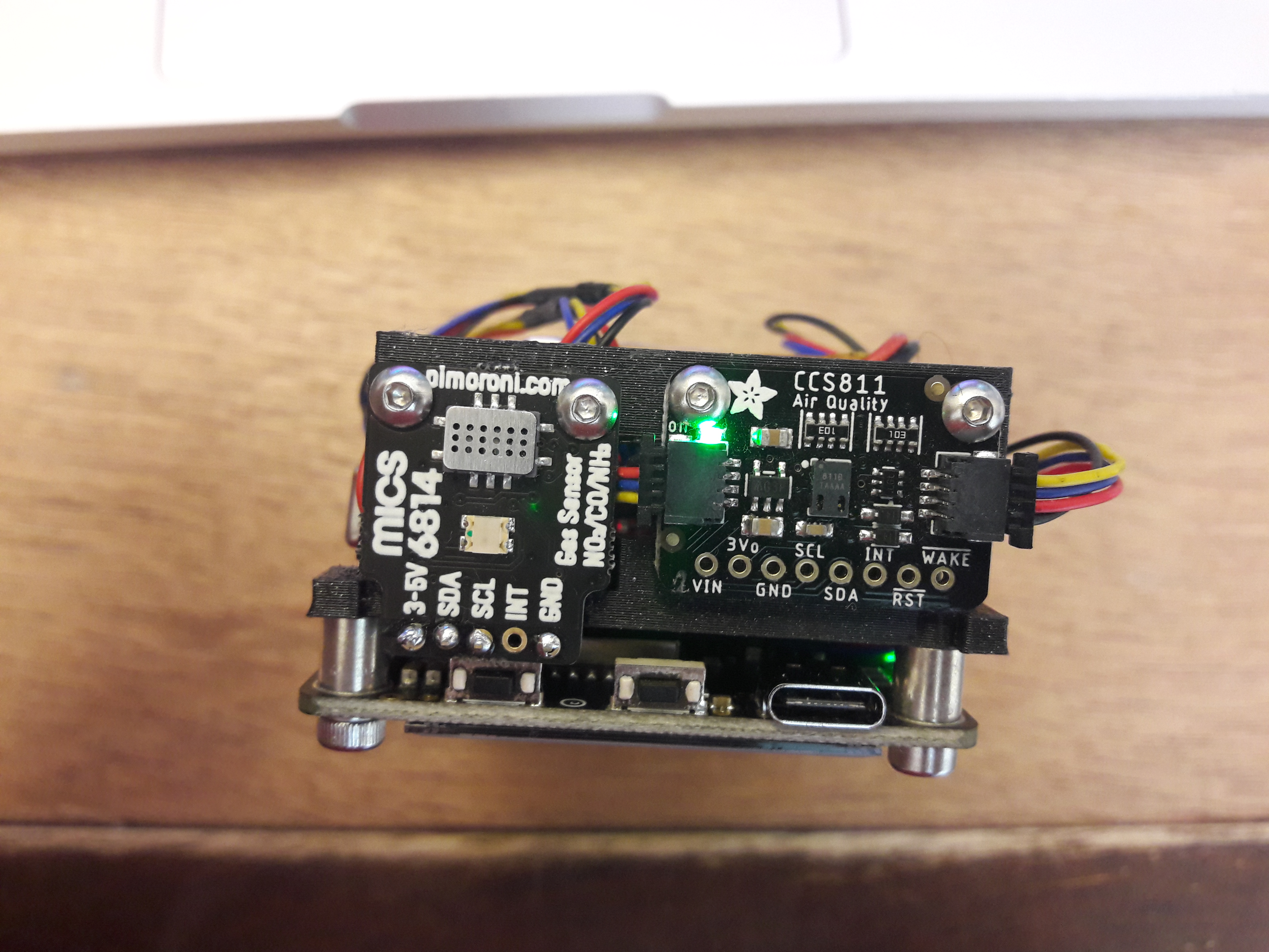
- Adafruit CCS811 Air Quality Sensor Breakout → Measures TVOC (total volatile organic compounds concentration) and estimates an equivalent CO2 concentration
- Adafruit PMSA003I Air Quality Breakout → Measures particulate matter concentration
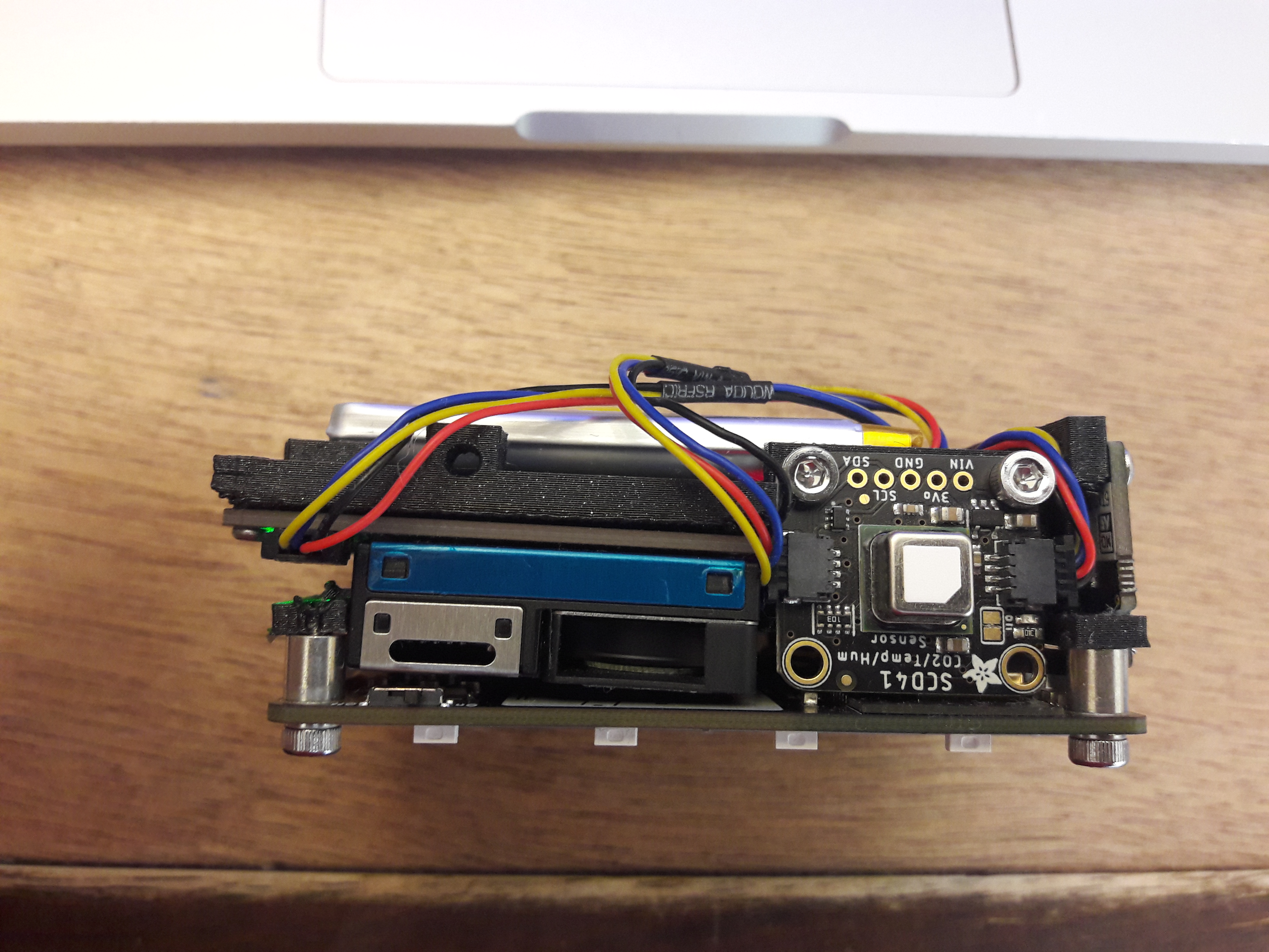
- Adafruit SCD-41 - True CO2 Temperature and Humidity Sensor → Measures the true CO2 concentration
- MICS6814 3-in-1 Gas Sensor Breakout (CO, NO2, NH3) → Measures some reducing gases (CO, NO2, NH3). This board does not have a StemmaQT/Qwiic connector, so I used a StemmaQT to male jumper cable
- BME688 4-in-1 Air Quality Breakout → Mostly a humidity/temp sensor, but also gives an air quality index. I believe the Adafruit brakeout was out of stock at the time, hence the choice of Pimoroni board instead.
- LiPo Battery Pack – 2000mAh
I also bought a Qwiic Power Switch, which can shut off I2C devices on an I2C bus, to reduce power consumption (more on that later).
An attractive alternative to the MagTag (which came out later) is the Pimoroni Badger 2040 which uses Raspberry Pi RP2040.
Testing the electronics #
I started by programming the MagTag to use CircuitPython.
CircuitPython is a fork of MicroPython maintained by Adafruit. Though mostly intercompatible, there are notable differences, and some libraries require some tweaking to get working. An important difference is that with CircuitPython the REPL does not have access to the state defined in the main
code.pyfile. This means that debugging is a little more difficult with CircuitPython in my experience.
Adafruit had nice libraries for most of the sensors :
For the MICS6814, I used this library from DanNduati, after tweaking the ioexpander (from micropython to circuitpython)
I also reused some of that code for the PCA9536 (Qwiic Power Switch).
Right away, the SCD41 CO2 sensor proved very useful. I could see the CO2 concentration rising in my room when closed and decrease to 500ppm with the windows open. 500ppm seemed high at first, but it seems to be the norm in large cities like Paris. The sensor also provided temperature and relative humidity data, which is nice.
Using the start_low_periodic_measurement method, I put it in low power mode with a satisfying current consumption of about 0.8mA.
The BME688 was not really interesting. The air quality metric it provides is difficult to map to any gas or particule concentration, which means it is difficult to interpret. I believe the sensor is most suitable for measuring temperature, humidity and pressure, with a very low current consumption (in the µA range). Having already the temperature and humidity from the SCD41, I quickly stopped using it.
The other sensors were less easy to sort :
- The CCS811 is nice, but consumes a lot more power (in the 5mA range) than the SCD41. The values is would give for the TVOC would also be low or null, making it less useful in my appartment.
- The PMSA003I sensor consumes a LOT of power : in the 80mA range. The values it returned were also fairly low and often null.
- The MiCS6814 was more complicated. There are libraries available to interpret the data collected, but some authors seem to question its accuracy. In the end, I mainly tried to check if the values were not null and somewhat varying. An issue with the sensor is that its I2C address interferes with that of the MagTag accelerometer (0x19).
For all sensors, blowing slowly on them with my mouth wide open would result in a spike in CO2/TVOC/PM2.5 values, showing they work properly.
In the end, I decided to include the CCS811, PMSA003I and MiCS6814 sensors, but behind the Qwiic Power Switch, to be able to turn them off for low power use.
I also hacked together a CircuitPython library for the Qwiic Power Switch using the MICS6814 driver as a base.
Designing a case #
Some constraints #
Now that I knew which sensors I needed, I could design the case for the device.
I wanted a compact device that could be hung on a wall. To avoid having dust accumulate in the wrong places, I realised I had to place the ports and sensors away from the top of the device.
However, I had not decided how I would orient the device in the first place.
I decided to expose all sensors and ports on two sides : one length-wise and one width-wise, allowing me to change my mind in terms of orientation later on.
I also knew I wanted the battery and its connector to be easily accessible, to measure the current draw and to later add an energy harvesting circuit.
I tried to physically arrange all sensors and boards with some cardboard, but I could not reach a compact configuration, so I resorted to CAD.
A clueless but quick method for creating 3D boards from Eagle #
My curent CAD package is Fusion360 from AutoDesk. AutoDesk also acquired Eagle and created a series of bridges between Eagle and Fusion 360. So at first, I thought I could open Eagle board files from Adafruit/Sparkfun and get in one click a 3D model in Fusion 360.
This did not happen. I spent a few hours trying to get the libraries right, but I am still confused and definitely not successful. However, I can quickly get the board with rough components placed, which is enough for me.
I ended up doing the following :
- Open the board in Eagle. I used the latest version of Eagle as of March 2022, Eagle 9.6.
- Click on the Manufacturing tab on the right. Click on the settings icon, and choose "SolderMask Color". Choose the appropriate color.
- Click on the Fusion 360 tab to create a new board there.
- In Fusion, open the generated model.
- Find the board packages, then right click and "Save a Copy".
- Open the new Packages model, it is now a normal 3D model, instead of a 3D PCB.
- In the data panel, click on the previous 3D PCB model and insert it in the current model.
- Break the link of the inserted model and delete its packages.
- Next clean up the model, removing the rectangle placeholders in front of holes, vias, etc.
- Then import all 3D models of important parts manually. I only did this for big components that matter in mechanical assembly.
Here is a resulting model, for the Adafruit SCD41 sensor board


A first attempt #
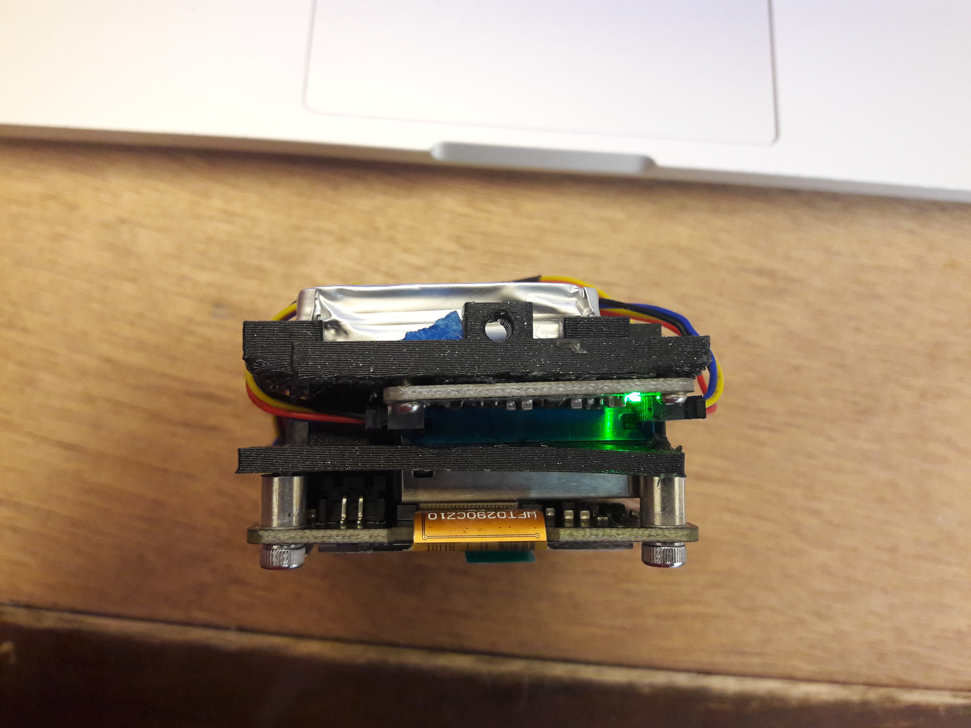
As I said, I was exploring with CAD different configurations. This meant that I was not modelling things with a reasonable method : no parameters, lots of complex sketches with many features that were edited later in the timeline...
Here is the resulting model :
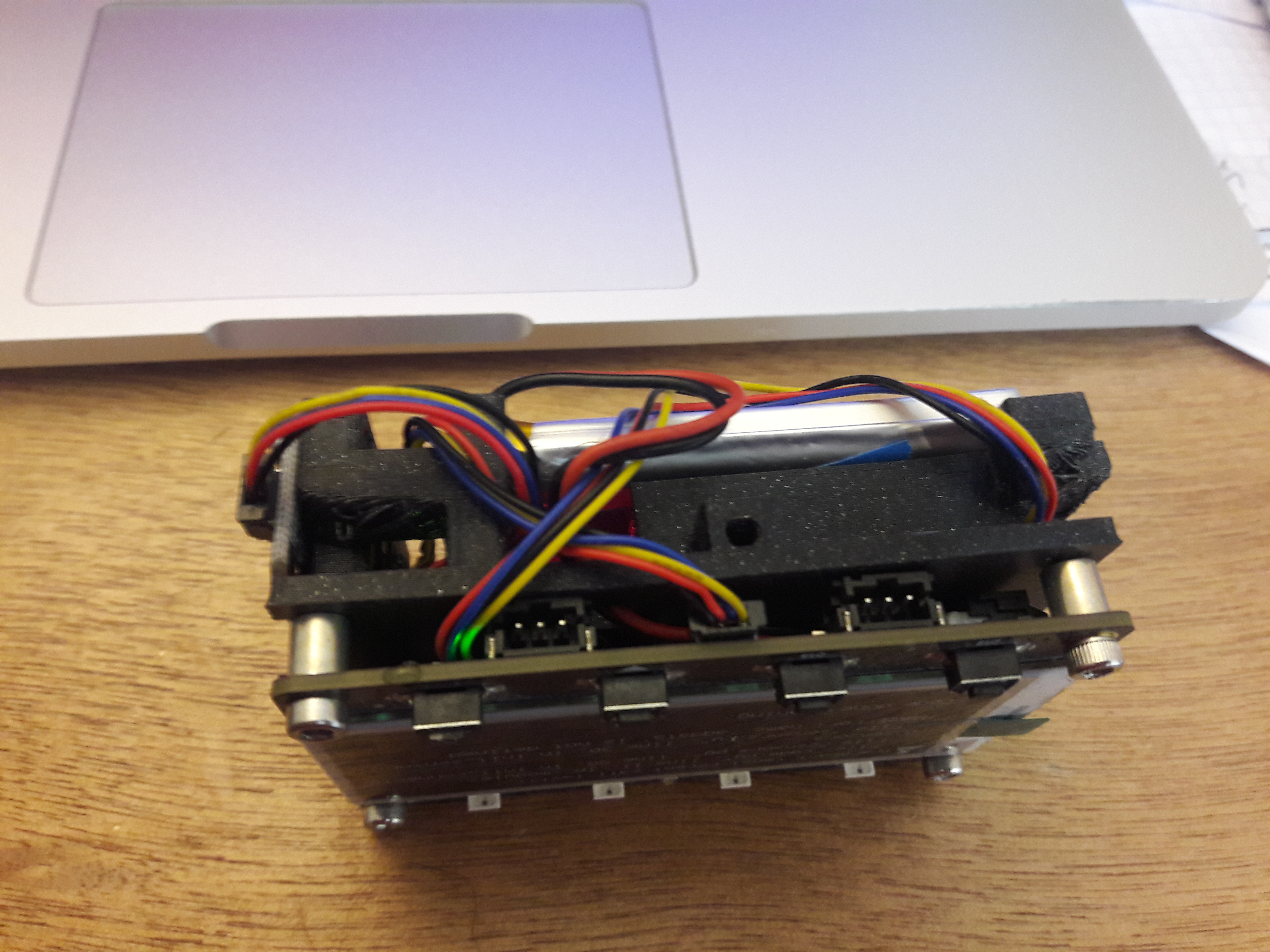
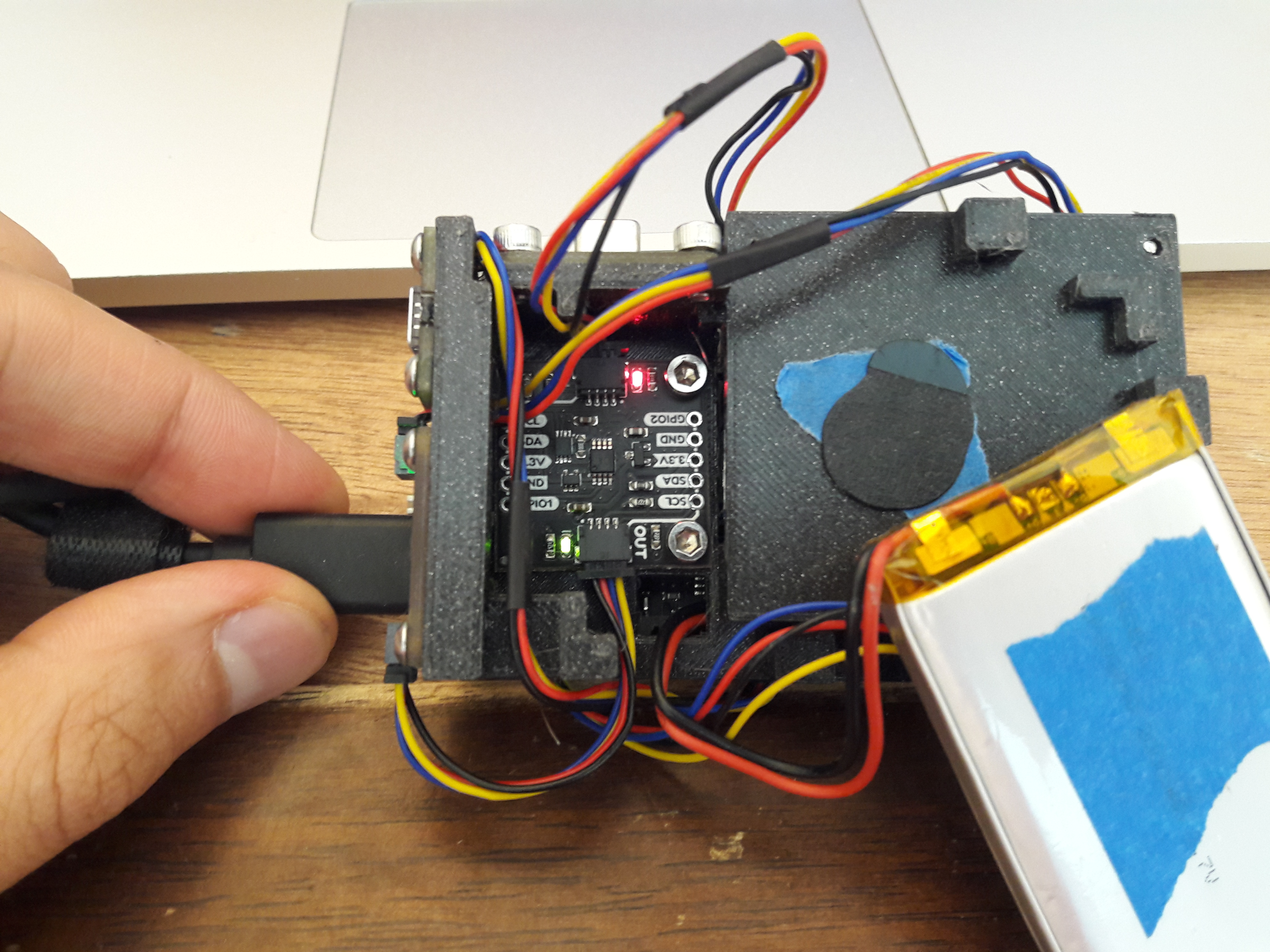
And here is the assembled device, before putting the covers on :
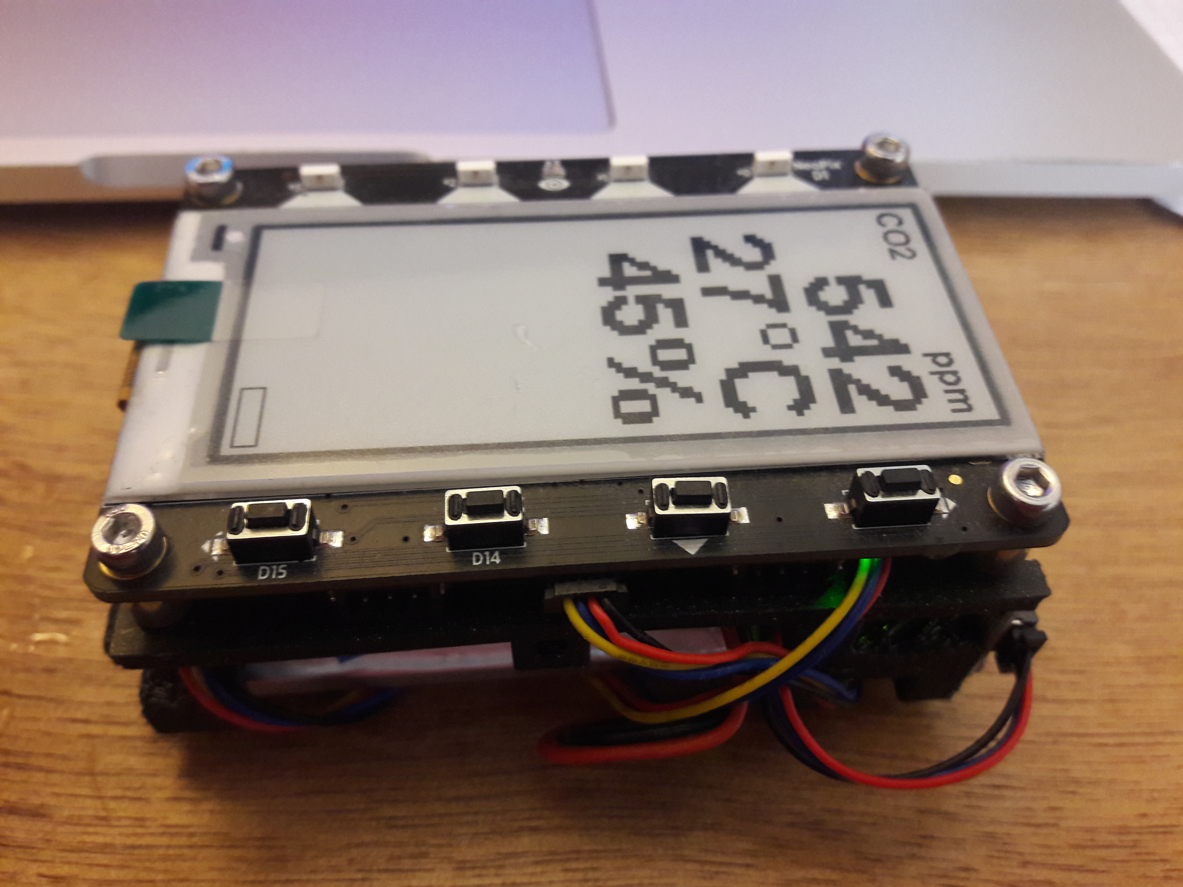
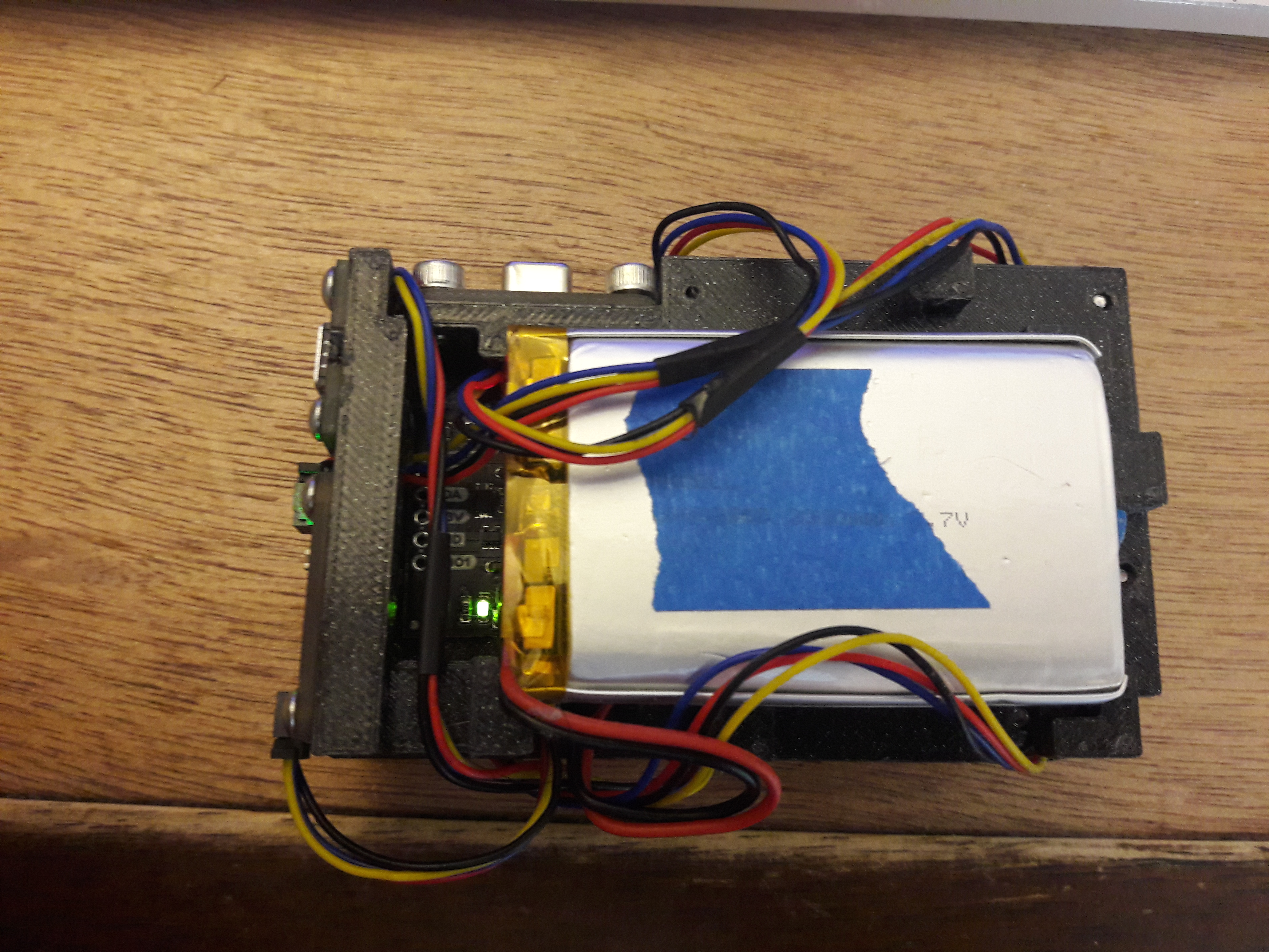
There were many problems with this version.
- The first one is that printing this model requires supports, which are a pain to remove cleanly.
- Another problem is that the bolts are just screwed directly into undersized holes in the plastic. This works for a very quick prototype, but I really don't like it. I should have used some metal threaded inserts (though some of board fasteners are quite small, at M1.7).
- The different boards are not properly supported and everything is twisted
- Finally, as expected, I did not spend enough time thinking about the wiring and the cable paths and clearance. So some cables are either very hard to plug in or simply crushed by adjacent parts...
Still, this is a functional first version and I learned a lot.
This is it for part one. In part two, I will try to program the board beyond the initial tests, design a new Qwiic compatible board for the MiCS6814 and design a new case.
- Previous: Tools I use